Electronics Production
First I opened the expample curcuit with Fusion Eagle and disabled all Layers I didn't need.

Then I exported as monochrome Image with dpi of 1500.

After that i cropped the image in Photoshop and saved it.

Additionaly I made a png where a rectangle with rounded corners was overlayed, for cutting out the curcuit-board later.

Then I went to fabmodules to translate the image into an Roland Mill File (.rml).

This were the settings I changed in the input fields on the right. After that I clicked calculate and saved the .rml file.

The result of the machine-code looked something like this. (This is for the outside image)

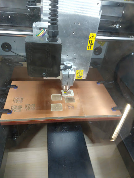
With the .rml files on a usb-stick it was ready for the cnc-mill. First I had to carefully guide the drillbit to its location and very precisely move it down toward the copperplate. This was done with the software on the laptop where you could move with fractions of millimeters.


After milling the inner part, I had to vaccum the copper particles out.

Also the drillbit had to be changed.

Now it was time for milling the outer part, which produced lots of powder.
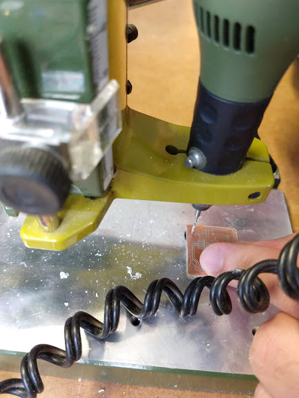
Before soldering I drilled the holes where the pins will go into.
Then it was time to solder the parts on. I started with the processor. First I fixed the position and then added tiny amounts of lead on each of the eight parts. After that I removed the lead that was to much with holding lötzinnlitze onto it and heating it up.

The result looked like this

So now it was time to connect the curcuit-board to an arduino with the given schematic. With that I was able to flash the software on it for the led to be blinking.


The program looked like this.

Just by selecting the Arduino in the port and by uploading the program everything was done. As soon as it was ready both, the arduino and the selfmade curcuit-board started blinking.
